

Blog
How to Design Parts for Laser Cutting: Fiber Laser vs. CO₂ Laser
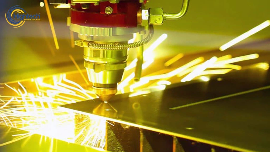
Table of Contents
Designing Laser Cut Parts is not just about drawing a shape—it is about designing with manufacturing reality in mind. The core difference between Fiber and CO₂ laser cutting design lies in how materials absorb energy and how that energy affects cut quality, cost, and production speed. From a DFM (Design for Manufacturing) perspective, Fiber laser design prioritizes ultra-precise nesting for metal parts, while CO₂ laser design requires careful kerf compensation and heat control for organic and non-metal materials.
In practical terms, poor design decisions increase machine time and material waste—the two biggest cost drivers in laser cutting. Well-optimized design files, on the other hand, allow parts to cut cleanly, stay dimensionally accurate, and move directly from the laser bed to assembly without rework.
Fiber vs CO₂ Laser Design Rules: The Role of Wavelength and Absorption
Before discussing specific design techniques, it is essential to understand why Fiber and CO₂ lasers behave differently. The laser source itself determines how forgiving—or unforgiving—your design will be once it reaches the cutting table.
Wavelength Physics: Why Design Rules Are Not Universal
Fiber lasers operate at a wavelength of approximately 1.06 µm, while CO₂ lasers operate at 10.6 µm. This difference directly impacts how energy is absorbed by materials during cutting. Metals absorb Fiber laser energy efficiently, allowing fast, narrow cuts with minimal kerf width. As a result, designers can create tighter tolerances, finer details, and more aggressive nesting layouts without compromising cut reliability.
CO₂ lasers, by contrast, transfer energy more gradually. Their wavelength is poorly absorbed by bare metals but highly effective on wood, acrylic, leather, rubber, and coated surfaces. This slower energy transfer creates a wider kerf and more thermal spread, which designers must account for during part layout and dimensional planning.
Material Compatibility: Designing for How the Laser “Bites”
From a design standpoint, Fiber lasers are ideal when the part is metal and volume matters. Thin stainless-steel brackets, aluminum panels, and mild steel components benefit from Fiber’s ability to “bite” instantly into the material, producing consistent results even in dense nesting scenarios.
CO₂ lasers shine in applications where material behavior matters more than speed. Organic materials expand, burn, or melt when exposed to heat, so designs must include allowances for edge darkening, corner radii, and kerf variation. Ignoring these factors often leads to burnt edges, dimensional drift, and rejected parts—especially in branding or decorative applications.
Understanding these absorption differences is the foundation of Design Parts for Laser Cutting that are both manufacturable and cost-efficient.
Design Considerations for Fiber Lasers (Metals & Precision)
When Designing Laser Cut Parts for Fiber lasers, the priority is precision-driven manufacturing with minimal waste and maximum throughput. Fiber laser cutting machines are unforgiving to poor design decisions—but highly rewarding when files are optimized correctly. Every choice, from hole diameter to part spacing, directly impacts cut speed, edge quality, and overall production cost.
Reflective Metal Design: Copper, Brass, and Aluminum
Fiber lasers excel at cutting reflective metals, but design discipline is critical. Copper, brass, and aluminum reflect energy at the start of the cut, which means the laser relies on rapid absorption once the pierce is complete. Designers should avoid placing small features too close to the pierce point and should ensure consistent material thickness across the part. Sudden thickness changes or overlapping contours can cause incomplete cuts or excessive heat buildup in reflective zones.
For aluminum in particular, sharp internal corners should be replaced with small radii wherever possible. This improves cut stability and reduces micro-burrs that increase post-processing time.
Minimum Feature Size: The 1:1 Rule Explained
One of the biggest advantages of Fiber laser cutting is the ability to produce small holes and fine details—but only within physical limits. A widely accepted guideline is the 1:1 ratio rule, meaning the minimum hole diameter should be equal to or greater than the material thickness. For example, a 3 mm steel sheet should not include holes smaller than 3 mm in diameter.
Violating this rule leads to tapered holes, incomplete penetration, or excessive edge roughness. From a cost perspective, these issues increase machine time due to slower cutting speeds or secondary operations, making the design inefficient even if it looks correct on screen.
read more: co2 laser cutting safety guidelines
Heat Affected Zone (HAZ): Designing Against Distortion
Although Fiber lasers generate a much smaller HAZ than traditional cutting methods, thin metal sheets can still warp if designs concentrate heat in one area. Long continuous cuts, dense internal features, or asymmetrical layouts all increase thermal stress.
Smart Design Parts for Laser Cutting distribute cuts evenly across the sheet and avoid isolating large solid areas surrounded by fine details. Balanced layouts reduce distortion and help parts remain flat after cutting, eliminating the need for straightening or rework.
Tabbing and Micro-Joints: Keeping Small Parts Under Control
Small metal components often fall through the cutting slats if they are fully separated too early. Designers solve this by adding micro-joints (tabs)—tiny uncut bridges that hold parts in place during cutting.
These tabs should be positioned in low-visibility areas and sized just large enough to prevent movement without requiring heavy post-processing. Proper tab placement improves automation, protects edge quality, and reduces downtime caused by tipped or jammed parts.
Design Considerations for CO₂ Lasers (Non-Metals & Thick Sections)
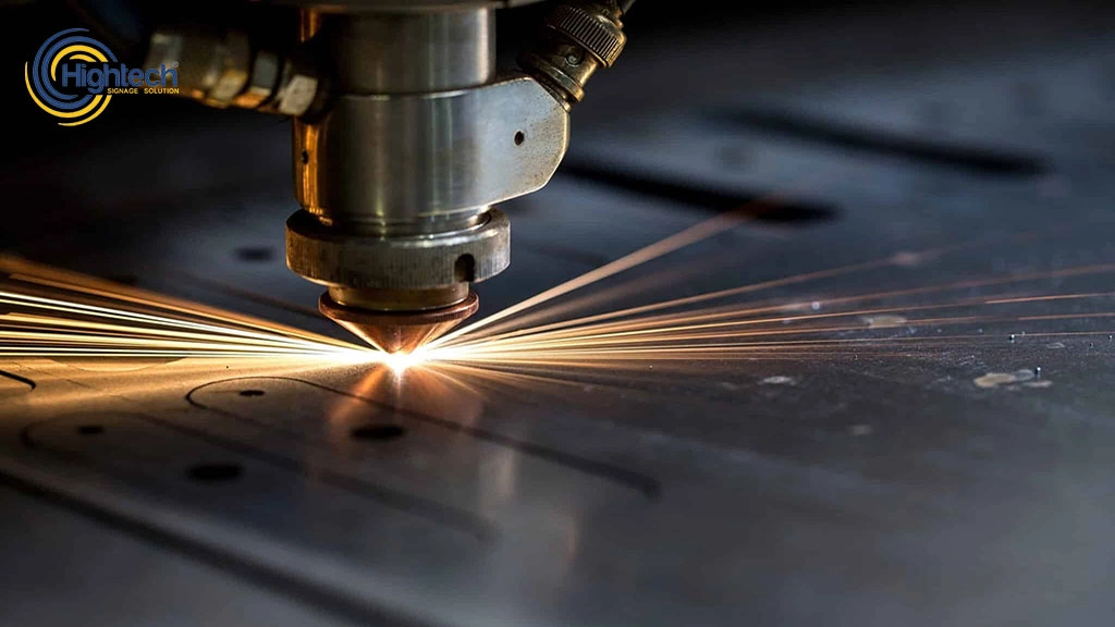
CO₂ lasers are versatile machines that excel in cutting non-metals and thick materials. When designing parts for CO₂ lasers, the primary goal is to account for the broader kerf width, heat distortion, and the potential for material burn, especially when cutting organics like wood or plastics. Understanding how these factors influence part design can help you achieve cleaner cuts and reduce rework.
read more: What Is Fiber Laser Marking?
Edge Quality in Organics: Minimizing Charring
One of the challenges when cutting organic materials such as wood, acrylic, or leather with a CO₂ laser is edge charring. The heat from the laser beam can cause combustion on the surface, resulting in darkened edges that may compromise the aesthetic quality of the part.
To mitigate this, designers should optimize the design file to reduce cutting time—this is typically done by ensuring that cuts are as smooth as possible, with clean paths that allow for quick passage of the laser. Additionally, keeping cut speeds high and minimizing dwell time (the time the laser spends on any given part) can help minimize charring. Also, adjusting laser power and speed based on material thickness will improve the finish by preventing excessive heating.
The "Flame-Polished" Edge: Achieving High-Quality Finishes on Acrylic
CO₂ lasers are famous for producing a flame-polished finish on materials like acrylic and plastic. This effect results from the high heat at the cutting edge of the laser, which melts the material, leaving a shiny, smooth edge. However, the material must be prepped properly to ensure this effect is achieved consistently.
To design for flame-polishing, ensure that the acrylic is clean and free of contaminants, which can affect the smoothness of the finish. Designers should focus on the cut speed and power settings, adjusting these to match the material thickness. Using appropriate cooling methods (e.g., air assist) during the cutting process will also help maintain the integrity of the edge finish.
Thick Material Radii: How to Handle Corner Radii in CO₂ Cutting
CO₂ lasers are particularly effective for cutting thick materials—especially when dealing with radii or thicker non-metals. However, cutting thick materials like wood or plastic with sharp corners is problematic due to the increased heat distribution, which can cause burns or deformation.
Designers should include larger radii in corners to help the laser cut more effectively. Sharp corners are hard for a CO₂ laser to process cleanly, and material might overheat and burn. Smooth, broad curves allow the laser to move more freely, reducing thermal buildup and improving the overall cut quality.
read more: co2 laser cutting settings
Kerf Compensation: Accounting for the Wider Beam Width
Unlike Fiber lasers, CO₂ lasers have a wider kerf width, which means that the cut will be broader than the beam diameter. To account for this, designers must compensate for kerf width in the design stage by slightly shrinking internal features and ensuring that parts have enough spacing between them to avoid interference during cutting.
A simple way to apply kerf compensation is to reduce the size of holes and inner cuts by a small fraction of the beam width (depending on the material thickness and laser settings). This adjustment ensures that parts are cut accurately, even with the wider beam of the CO₂ laser.
Universal Laser Cutting DFM (Design for Manufacturing)
Effective Designing Laser Cut Parts requires more than just knowing the laser type—it demands DFM principles that reduce errors, material waste, and production time. By following universal best practices, designs become machine-ready, cost-efficient, and repeatable across both Fiber and CO₂ lasers.
- Vector Hygiene: Ensure all paths are closed and remove duplicate lines.
Duplicate or open paths can cause overcuts, wasted material, and longer machine time. - File Formats: Use .DXF or .SVG instead of raster images.
Vector files are scalable and precise, allowing the laser to follow exact paths without pixelation. - Nesting Strategies: Arrange parts efficiently on the sheet.
Proper nesting maximizes material usage, reduces cutting time, and lowers overall production cost.
Bridge Cuts: Add micro-bridges for delicate or stencil-style parts.
Bridges prevent small cutouts from falling through prematurely, keeping intricate shapes intact.
Fiber vs. CO₂: Material & Design Comparison Table
When Designing Laser Cut Parts, choosing the right laser depends heavily on material type, part complexity, and production volume. A simple comparison helps designers make faster, more cost-effective decisions.
Feature | Fiber Laser | CO₂ Laser |
Material Suitability | Metals (Steel, Aluminum, Copper, Brass) | Non-Metals (Wood, Acrylic, Leather) & Coated Metals |
Kerf Width | Narrow (0.05–0.2 mm) | Wider (0.1–0.5 mm depending on thickness) |
Precision | Very high (tight tolerances, small holes) | Moderate (larger minimum feature sizes) |
Cutting Speed | Extremely fast on thin metals (<6 mm) | Slower, especially on metals |
Heat Affected Zone | Minimal | Larger, may require design compensation |
Feature Size | Can achieve 1:1 hole-to-thickness ratio | Minimum features limited by kerf and material |
Nesting Efficiency | High, parts can be tightly packed | Moderate, spacing needed for heat control |
Typical Applications | Industrial metal panels, precision components | Signage, decorative parts, thick organics |
Common Design Pitfalls to Avoid
Even the best lasers can produce poor results if the design files are flawed. Awareness of common pitfalls ensures that Designing Laser Cut Parts translates into efficient production, minimal material waste, and clean edges.
- Open Loops: Avoid paths that don’t fully close.
Open loops can leave parts partially attached or “hanging,” causing jams or miscuts during cutting. - Inadequate Spacing: Prevent the “webbing” effect.
Parts placed too closely together may fuse slightly, break during removal, or distort the material. - Font Selection: Match text to the intended cut mode.
Stencil-style fonts are required for fully cut text, while engraved fonts are better for etching; improper selection can ruin readability or part integrity.
By checking these factors early, designers save time, reduce material waste, and ensure the laser performs at maximum efficiency for both Fiber and CO₂ systems.
Frequently Asked Questions
1. Can I use the same design file for both Fiber and CO₂ lasers?
Generally no; Fiber designs focus on metals and precision nesting, while CO₂ requires kerf compensation and heat management for organics.
2. Why does my CO₂ laser design have burnt edges on wood?
Burnt edges result from slow cut speeds, excessive laser power, or overly dense internal paths; optimizing these reduces charring.
3. Is Fiber laser cutting more cost-effective for high-volume designs?
Yes; Fiber lasers cut metals faster, with minimal kerf and HAZ, reducing material waste and machine time.
4. What is the best software for designing laser-cut parts?
Vector-based programs like AutoCAD, CorelDRAW, or Adobe Illustrator are ideal for clean, scalable, and machine-ready files.
Latest contents