

Blog
How Does a CNC Router Work?
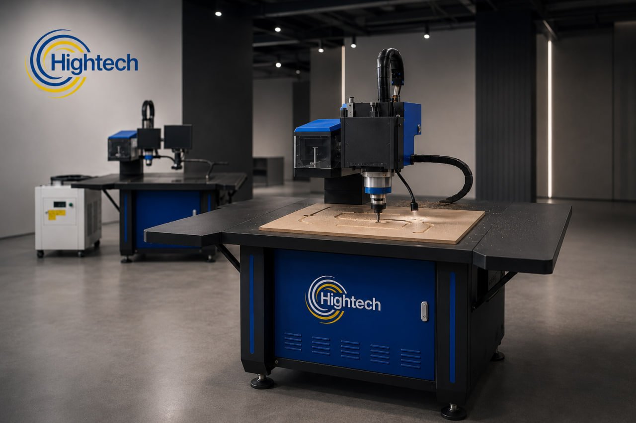
Table of Contents
A CNC router turns a digital design into a physical part by following computer-controlled cutting instructions. The operator creates or imports a design, uses CAM software to calculate toolpaths, secures the material, sets the machine’s reference point, and starts the program. The controller then coordinates movement along the X, Y, and Z axes while a rotating cutting tool removes material.
The complete CNC routing process also depends on the machine’s frame, spindle, motion system, worktable, tooling, software, and setup. Understanding how these elements work together helps production buyers evaluate a router for their materials and output.
Quick Fact
CAD defines the part; CAM converts it into toolpaths and G-code.
The controller coordinates X, Y, and Z motion as the spindle cuts.
Vacuum or clamps hold the sheet while work zero sets the starting point.
A validated file can reproduce the same part with consistent geometry.
What Is a CNC Router?
A CNC router is a computer numerical control machine that cuts or engraves material with a rotating tool. Unlike manual routing, the operator does not guide the cutter by hand. The machine follows programmed coordinates and feed movements, allowing the same geometry to be reproduced across multiple parts.
Most flatbed industrial routers use three linear axes. The X axis moves across the table, the Y axis travels along its length, and the Z axis raises or lowers the cutting tool. Depending on the machine configuration and tooling, a router can profile an outside shape, clear a pocket, drill holes, engrave text, cut grooves, or carve a three-dimensional surface.
Typical work includes acrylic letters, PVC and MDF signs, channel-letter faces and backs, display panels, cabinet parts, doors, templates, and repeated branding elements. The correct machine and parameters depend on the substrate, thickness, part size, edge-quality target, and output.
How Does a CNC Router Work Step by Step?
1. Create or Import the CAD Design
The process starts with a digital drawing. CAD software defines the size and geometry of the finished part using vectors, curves, holes, pockets, or 3D surfaces.
Open contours, duplicate lines, incorrect units, or overlapping geometry can create unwanted cuts. The designer must account for tool diameter, inside-corner radius, material thickness, and workholding.
2. Generate Toolpaths in CAM Software
CAM software translates the drawing into machining operations. The programmer selects the tool and defines its path, depth, direction, feed rate, spindle speed, step-down, and entry method.
Toolpaths may cover profiling, pocketing, drilling, engraving, or 3D carving. CAM can also add holding tabs and lead-in moves. Simulation helps reveal collisions, missed areas, and inefficient travel before machining.
3. Convert the Toolpaths Into G-Code
After approval, a post-processor converts the toolpaths into controller-readable instructions, commonly called G-code. They define position, speed, spindle commands, and machining states.
The post-processor must match the controller. Code formatted for another control system can behave incorrectly. Published HT R3 Q information identifies G-code/HPGL support in its specified control environment, showing why software compatibility must be confirmed.
4. Secure the Material and Set the Work Zero
The workpiece must stay flat and motionless. Routers may use a vacuum table, T-slot clamps, fixtures, or combined methods. Vacuum is efficient for sheet nesting; clamps suit smaller or irregular parts. A spoilboard protects the table during through-cuts.
The operator installs the bit and sets the work zero, where programmed X, Y, and Z coordinates begin. Tool length is set manually or with a tool setter. A wrong origin or height can shift the part, cut too deeply, or damage the surface.
5. The Controller Directs X-, Y-, and Z-Axis Movement
The controller reads the program and commands the motors and drives. They move the gantry, carriage, and Z assembly through linear guides and transmission components.
Coordinated axis motion lets the tool follow curves, diagonals, and complex profiles. Most flat-sheet work uses three axes, while rotary or multi-axis machines add motion possibilities. Buyers can compare 3-axis, 4-axis, and 5-axis CNC routers.
6. The Spindle and Router Bit Remove Material
The spindle rotates the tool while the machine advances it through the workpiece. Straight or compression bits suit panel cutting, V-bits create lettering and chamfers, ball-nose tools produce 3D carving, and specialized tools process plastics or approved non-ferrous materials.
Cut quality depends on spindle speed, feed rate, tool geometry, and depth. Excess heat can melt plastic; unsuitable feeds can burn wood or shorten tool life. Effective chip removal protects finish and hold-down.
7. Inspect, Finish, and Repeat the Part
The operator checks dimensions, edges, holes, surface finish, and tabs. The part may then require deburring, sanding, polishing, cleaning, or assembly.
An approved file can produce repeat parts with consistent geometry. Tool wear, material variation, vacuum loss, and setup changes can still affect output, so shops retain approved files and setup values.
Main Parts of a CNC Router and What They Do
Frame and Gantry
The frame supports the table and motion system; the gantry carries the spindle. Rigidity limits flex and vibration that can reduce accuracy or leave tool marks.
Spindle, Collet, and Cutting Tool
The spindle supplies rotation and power, the collet grips the shank, and the bit cuts. Tool diameter, cutting length, flute design, and material compatibility must suit the operation. Poor tool holding causes runout, chatter, or inaccurate cuts.
Controller, Motors, Drives, and Linear Motion System
The controller interprets the program, drives regulate motor movement, and linear-motion components convert commands into travel. Together they influence path accuracy, acceleration, direction changes, and speed under load.
Worktable, Vacuum Hold-Down, Clamps, and Spoilboard
The worktable provides a stable surface. Vacuum zones secure sheets; T-slots and fixtures provide mechanical clamping. Hold-down is critical when nesting small parts. The HT R3 Q CNC router is a sign-and-panel example with vacuum hold-down for approved acrylic, PVC, wood, MDF, polycarbonate, and ACP work.
Automatic Tool Changer, Tool Setter, Dust Collection, and Cooling
A tool setter measures tool length; an automatic tool changer switches cutters; dust extraction removes debris; and spindle cooling manages heat. Availability varies, so buyers must confirm the exact configuration.
What Operations Can a CNC Router Perform?
Cutting, Profiling, Pocketing, Drilling, and Engraving
Profiling follows the outside or inside boundary of a part. Pocketing removes material within a defined area. Drilling creates programmed holes, while engraving produces text, logos, identification marks, or decorative detail. Multiple operations can be combined in one file, provided the tooling and machine configuration support them.
2D and 3D Carving, Grooving, and Repetitive Production
Two-dimensional work keeps features primarily in the X-Y plane with controlled cutting depths. Three-dimensional carving varies Z height continuously to produce reliefs, molds, patterns, and sculpted surfaces. Routers can also cut channels, dados, rebates, and grooves. Once a program and setup are validated, the machine can reproduce the same part or nested sheet layout across a production batch.
What Materials Can an Industrial CNC Router Cut?
Industrial routers commonly process wood, plywood, MDF, acrylic, PVC, polycarbonate, plastics, sign board, ACP, and compatible composites. Selected machines may also route approved aluminum or other non-ferrous materials when the tooling, lubrication or chip removal, spindle capability, rigidity, and cutting parameters are suitable.
Compatibility is never based on material name alone. Grade, thickness, panel construction, desired finish, and production speed all matter. Flexible media such as vinyl, fabric, light-box cloth, leather, rubber, or foam generally require a drag knife, oscillating knife, or combined router-and-blade system rather than a standard rotating bit. Steel and dedicated sheet-metal cutting are normally better matched to other equipment, such as a fiber laser.
Hightech’s range of industrial CNC router machines includes compact, full-sheet, higher-power, automatic-tool-change, T-slot, and combined router-and-blade configurations. A sample cut is the safest way to verify edge quality and cycle time for a specific material.
Common Industrial CNC Router Applications
Sign makers route dimensional letters, acrylic logos, PVC signs, channel-letter faces and backs, wayfinding panels, display parts, and repeated branding panels. Vacuum hold-down supports nested small parts.
In woodworking, a CNC router machine for woodworking can process MDF and plywood panels, doors, drawer fronts, patterns, templates, and selected joinery. CNC routers for cabinets improve repeatability, while a CNC router for kitchen manufacturing standardizes panel components. Not every router is a complete nesting or drilling center; tool changing, drilling, software, dust extraction, and vacuum zoning must match the plan.
Commercial panel processors and fabrication shops use routers for prototypes, fixtures, enclosures, display components, and repeated parts. Businesses working with both rigid sheets and flexible media may need a combined system. Within the Hightech lineup, the HTR5 combines a spindle router with a vibrating blade, while the HT RX6 is positioned for multi-tool production with automatic tool changing. The HT R3 Q supports general sign and panel work, and the HT R3 E provides a T-slot approach for mechanically clamped workpieces.
The job determines the best configuration. Buyers should document material grade and thickness, sheet size, operations, daily volume, smallest parts, edge standard, electrical supply, software workflow, and dust-management needs.
Frequently Asked Questions
How does a CNC router work step by step?
CAD defines the geometry, CAM creates toolpaths, and a post-processor outputs controller-compatible code. The operator secures the material, sets the tool and origin, and starts the program. Coordinated axis motion guides the rotating cutter. After inspection, the approved setup can produce repeat parts.
What are the main parts of a CNC router?
Main parts include the frame, gantry, spindle, collet, bit, controller, motors, drives, motion system, worktable, hold-down, and spoilboard. Options may include a tool setter, automatic tool changer, vacuum pumps, dust interface, and spindle cooling.
Does a CNC router use CAD, CAM, and G-code?
Usually. CAD defines geometry, CAM creates toolpaths, and a post-processor converts them into controller instructions. G-code is common, but the accepted format depends on the controller, so compatibility must be verified.
What materials can a CNC router cut?
A suitable router can process wood, MDF, plywood, acrylic, PVC, polycarbonate, plastics, sign board, ACP, and compatible composites. Approved non-ferrous work needs the correct machine, tooling, and parameters. Flexible media generally need a blade; steel needs another cutting technology.
Is a CNC router fully automatic?
The cutting cycle is automatic, but the workflow is not hands-off. An operator prepares the file, selects tooling and parameters, secures material, sets references, checks safety and extraction, monitors the job, and inspects output. Automation reduces manual steps but does not replace process knowledge.
Latest contents